To the west of Paris, a new train line is in development to serve both Parisians and the surrounding area. As part of the Eole project, the new RER E line will introduce 55km of new rail track, as well as new stations along the route. Set to open to passengers in 2024, the terminus of the new line is in the Mantes-la-Jolie triangle.
COGECI, a French design office with extensive experience, has the responsibility of the execution studies of a new, 600-meter-long viaduct at Mantes-la-Jolie for the new line. Once completed, the bridge will enable rail traffic in the area to flow more smoothly. COGECI used Allplan Bridge for the first time on this project, and the experience convinced them that a BIM-enabled solution specifically for bridges was the way forward.
Project Background
The project included the creation of sidings and a maintenance workshop near the bridge. In addition, there are several existing railway tracks nearby, so the space for the new structure was limited. The S-shape of the bridge meant that many of the existing railway tracks would be located close to the bridge supports, so the correctness of the location was of the utmost importance.
The bridge itself is a steel rail bridge with lateral beams, composed of three decks: 4 spans for a length of 200 meters, an inert span of 50 meters in the middle, and finally 7 spans for a length of 370 meters, which is the most important part. At each end, there is an access ramp with retaining walls and embankments. While the structure is mainly made of steel, the bridge also incorporates a reinforced concrete slab. COGECI studied all the reinforced concrete elements of the project, including those used in the supports, piers, abutments, and retaining walls.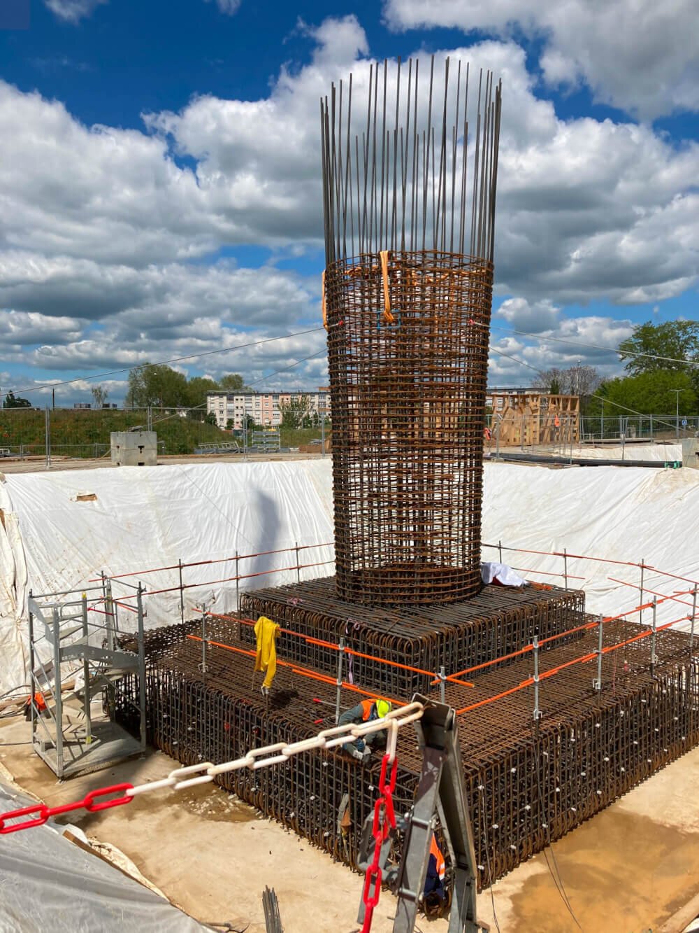 © Bouygues TP / Cogeci; Reinforcement of the footing and shaft of Pile P4
Implementing BIM for Bridges
Building Information Modeling (BIM) was requested by the client for several reasons, including improved project documentation, enhanced design and construction quality, and better communication with local residents as well as various stakeholders. In addition, the client wanted to make use of the data generated during the project for future maintenance, operation, and demolition.
BIM Level 2 was specified for this project, where each discipline prepared a sub-model that was then combined into a federated model using IFC and OPEN BIM. This way, any clashes or interfaces between different disciplines could be identified early and a digital as-built model created easily. It was also easier to visualize the interfaces between the bridge structure and the infrastructure of the future sidings.
There were three main models for the bridge: the model of the pile foundations, the civil engineering model, and the steel fabricator’s model. Using Allplan to import the IFC files, COGECI were able to check the interface between the reinforced concrete structure and the steel framework, as well as the framework itself. In addition, the model of the steel framework was used to model the concrete slab.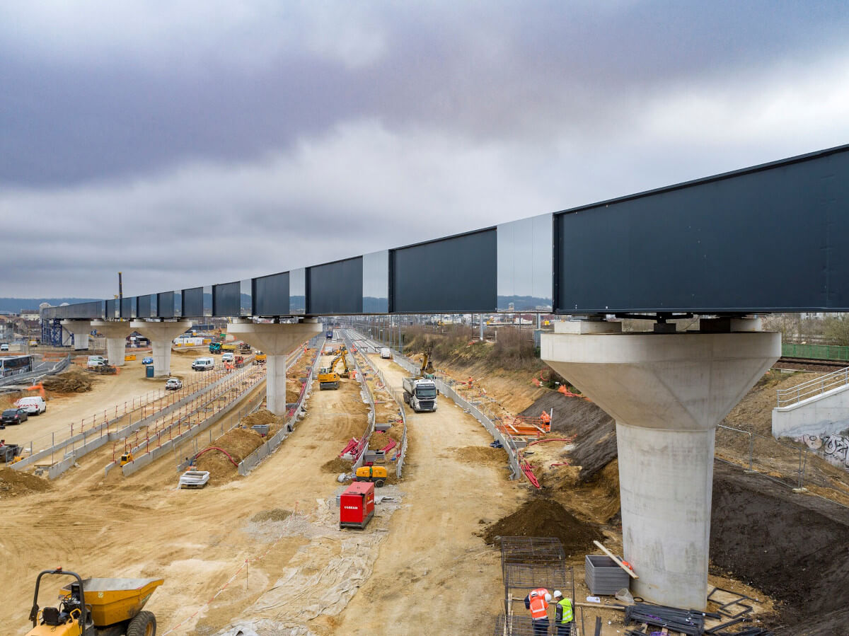 © Bouygues TP / Cogeci; Longitudinal view of the structure from C0
Easy Bridge Modeling
Using a LandXML file, the alignment data for the track route was imported using Bimplus so that the supports could be precisely located. The file contained 1,000 meters of track, but Allplan Bridge enabled the easy variation of the track route despite the size of the project. After creating cross-sections of the two bridge rails, the rest of the track could be quickly modeled by extruding the sections along the longitudinal profile.
The track superelevation varies along the route, which was sometimes difficult to see in areas where the gradient was minimal. However, the 3D model allowed a much better visualization of the track so the sections with superelevation could be seen.
The bridge model was then exported to Allplan Engineering, where the supports were modeled. The bridge piers are highly architectural and as a result, the geometry is atypical. However, the modeling tools that Allplan offers – such as Extrude, Loft, and Trajectory Scan – enabled the modeler to understand the complex pier geometry on a more intuitive level.
From here, it was easy to extract two-dimensional views of the model to produce the formwork and reinforcement plans. Other information – such as the volumes of concrete and surface area of formwork – could be quickly generated by the bridge design software.
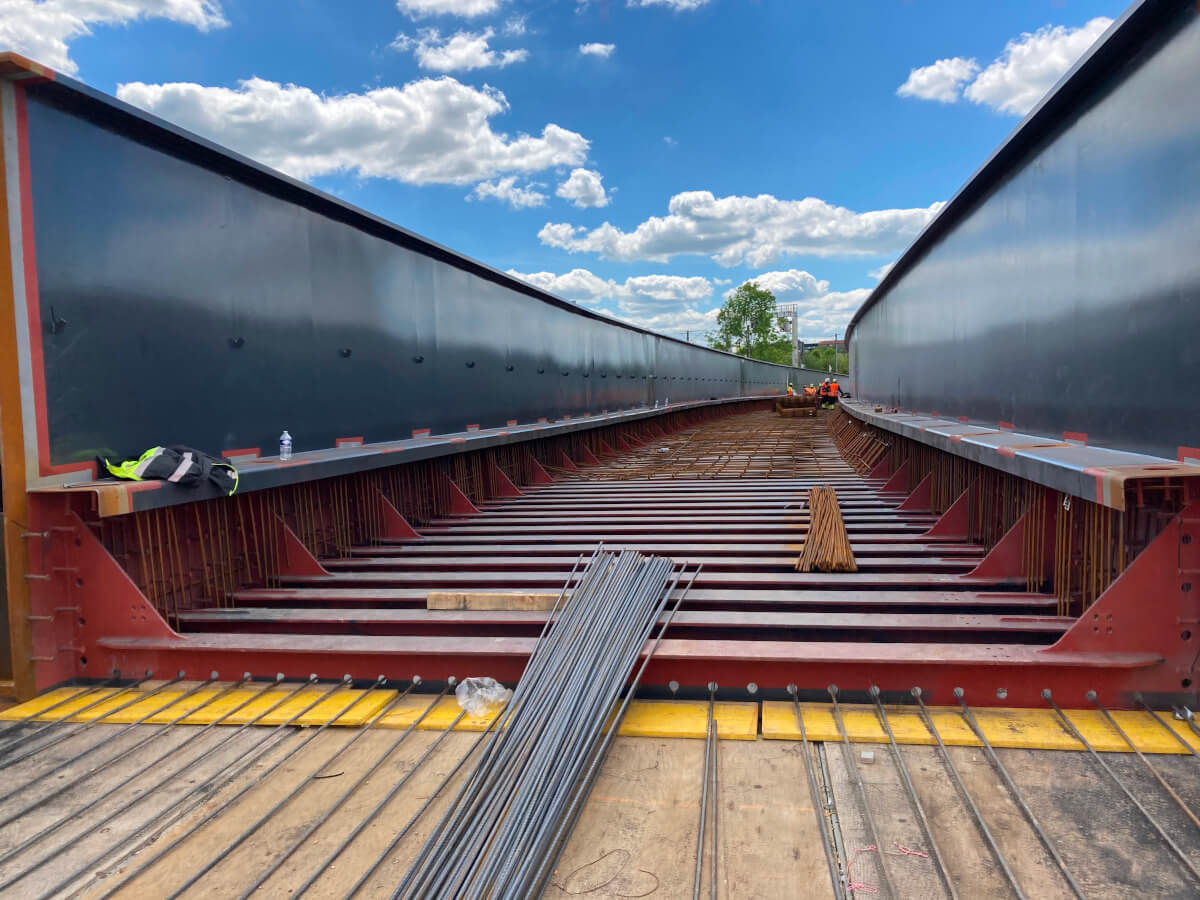 © Bouygues TP / Cogeci; Interior view of the RaPL deck structure
Conclusion
The Mantes-la-Jolie viaduct was COGECI’s first large-scale use of Allplan Bridge and Allplan Engineering, yet the experience has convinced them to continue to use bridge design software. The added value of the 3D visualizations provided much better insight than 2D drawings, as well as providing a more organized approach to coordinating with other disciplines.